Deployable, reconfigurable, affordable and repurposable naval bases of the future
Lim Soon Heng1, Professor Wang Chien Ming2, Dirk Jan Peters3
1
Managing Director EMAS Consultants LLP, Singapore;
2Director Engineering Science Program, National University of Singapore;
3 Hydraulic structures expert Royal HaskoningDHV, Netherlands.
ABSTRACT
This paper discusses a revolutionary idea for naval bases of the future. Even as rising sea level inundates land, the human population relentlessly pushes towards the coast. New space solution is needed. Mega floats offer this solution. Mega floats are deployable, easily scalable, and may be reconfigured as needs change. Old floats may be repurposed when no longer relevant to the original intent. This and other features make megafloats a more ecologically acceptable space solution. Structurally the technology is proven. Mechanical and electrical systems exist to provide support to the floats dispensing cable and pipe links to shore. For the navy, the mobility of megafloats offers strategic advantages. They can be repositioned to meet the shifting military challenges as world power rebalances.
NAVAL BASES CHALLENGED BY A CHANGING WORLD
When Nelson defeated Napoleon at Trafalgar in 1805, the world had about one billion people. Today it has 7.3 billion, 44% of which, according to a UN study, has migrated to the coast. Concurrently with rising sea levels, coastlines are receding at an alarming rate threatening the viability of many mega cities and ports.
Cities such as London, Venice and Rotterdam have put in place flood defence systems. Others like Singapore have revised building codes to address the problem. These measures may not be adequate in the light of new predictions of a one to two meter rise in sea levels within the next hundred years. In the US, the Proceedings of the National Academy of Science predict Miami and New Orleans to fall under rising sea level.
Rising sea levels mean new naval bases must be designed about one to two metres higher than existing ones. This however would mean that the entire hinterland have also to be raised by the same amount all the way back to a point where the contour line is consistent with the level of the new marine structures. Depending on the specific topography, this may not be practical.
Thus, we have a situation where it could be impractical to build new onshore naval bases and if it were, they would have to compete for water front space claimed by the movement of the sea moving inland and humanity moving in the opposite direction.
Bases in Davenport (UK), Toulon (France), Mumbai and Norfolk (US) built about two hundred years ago no longer have the easy option of setting back their boundaries to expand their facilities. They are straitjacketed by peripheral urbanisation.
Proposed new sites meet with opposition as in Karwar (India), Okinawa (Japan) and Jeju (S Korea) from locals, who see them as threats to the ecological and social environments or even livelihood. The basing of nuclear powered submarines and weapon systems in existing naval bases also incur the ire of residents as in Faslane (UK), and Bangor (US) for fear of collateral damage in a hostile event or an accident arising from an engineering deficiency.
Reclaiming land to build bases attracts protests from NGOs as they harm the biodiversity of marine life. The UNEP (United Nations Environment Programme) also takes a serious view of the degradation of the agro-economy of the area around the burrow pit. Exporting sand for reclamation purposes is fertile ground for corruption and political agitation.
Two hundred years ago, it was easy to find land to build bases as large those in Portsmouth in the UK, Toulon in France and Norfolk in the US. The land needs to be in militarily strategic locations, with deep sheltered waters and geologically stable for the construction of docks, and piers. As the years go by such criteria are more and more difficult to fulfil. Land reclamation is not always a viable solution. At depths exceeding 20 meters, it is prohibitive. The cutting of land or the dredging of sand for reclamation is damaging to the environment. The covering of acres of seabed with foreign material smothers the marine ecosystem underneath and around it.
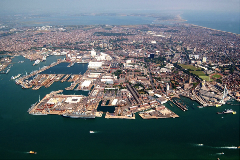
Fig 1: Her Majesty’s Naval Base Portsmouth surrounded by urban developments
VLFS (Very Large Floating Structures) AS NAVAL BASES
The most remarkable example of the use of VLFS is the temporary Mulberry harbour in Normandy, which provided logistic support to the Allied Forces between June 1944 and the conquering of Antwerp and the mouth or the Scheldt. The conglomerate of floating structures was immense. The new technology enabled the harbour to be built undetected off-site and sprung into action catching the Nazis off-guard.
VLFS are a game changing solution for marine structures of the future. They not only overcome the problems mentioned above but also provide many advantages over traditional bases.
Although there is no comprehensive floating naval base, all the necessary elements, jetties, docks, cranes, workshops and accommodations have floating equivalents for decades. Developments in offshore exploration and production of oil and gas have added vast knowledge in this field.
History has shown that military bases on foreign soils are prized targets. In the hands of the adversary, they tip the balance in their favour, triggering a defining moment in history. Examples include the HMNB at Sembawang in Singapore when the Japanese routed the British, Cam Rahn Bay in Vietnam when the Vietcong forces broke the US defence, Clark Airbase in the Philippines, which fell to the Japanese in 1942, and at Toulon and St-Nazaire in France. Upon the departure of the US forces, the Vietnamese invited the Russians to make use of Cam Rahn Bay to counter the US presence in Asia. These events show that “grounded” naval bases can easily revert from an asset to a liability in the course of a conflict. Had those structures been floating it would be possible to remotely detonate massive explosives hidden in the floats when they are populated with enemy ships: a subterfuge reminiscent of the Trojan Horse.
The US base in Okinawa has been a thorny issue for years with the local residents, 85% of whom want the US base out. In recent months it protests have resurfaced to haunt the Japanese PM just when he needs the US presence to counter Chinese assertiveness. Had the base been on floating structures, such friction with the host country need not occur. The base could be located near but outside Okinawan waters and local politics.
The Clark Airbase’s chequered history came to an ignoble end in 1991. It was “systematically looted and left abandoned for several years” (Wikipedia). Had the base been constructed on VLFS, it could be relocated to another militarily strategic location and revitalised. Alternatively, it could be disassembled and modules could be towed nearer to city centres and be converted to serve some humanitarian purpose such as hospital, school, apartments or floats to harvest wind energy or potable water from rain precipitations.
In the dynamics of today’s geo-politics when friend turn foe and foe friend as different shades of politics come into play every four or five years between super powers, military bases need to be nimble, to be able to pack and leave one location for another leaving nothing behind that one may later regret. A cluster of VLFS forming a naval base can be unmoored, wet or dry towed in a matter of days, to a politically less sensitive area.
Business Insider Singapore on August 11, 2015 reported that China’s military wants to “create large modular artificial islands that can be repositioned around the world as necessary”.[1] The US had similar plans known as the Joint Mobile Offshore Base (MOB) conceived during Gulf War. The structure included a 6000–feet airstrip. “A report presented to the U.S. Congress in April 2000 identified that such a base was technologically feasible and could be built by United States industry. A further report in 2001 by the Institute for Defence Analyses concluded that the estimated US$5 billion to US$8 billion was less cost effective than alternate solutions” (Wikipedia on Mobile Offshore Base).
The melting of the ice caps, due to global warming has military implications not the least for the US and Russia. For the hostile environments of the Arctic and Antarctic, constructing military bases on site is impossible. VLFS technology enables fully out fitted and ready-to-go bases to be constructed in favourable climes for service anywhere. The offshore oil and gas industry is littered with examples of VLFS servicing in fields thousands of kilometres away from where they were constructed.
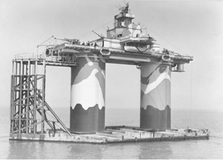
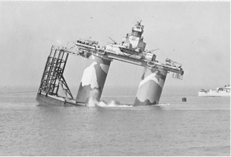
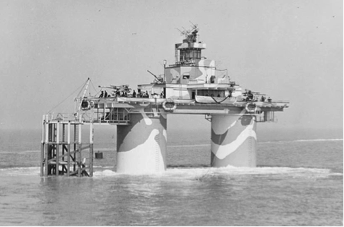
Fig 2: Historic floating moveable fortress for British Navy
PROVEN PLATE LIKE FLOATING STRUCTURES
While ships and oilrigs are floating structures, they behave differently from long and wide rectangular structures under the action of waves. The latter are not as stiff and their flexural response to long period waves is the subject of research by a number of investigators.
Though not as common as structures for transportation, oil exploration and production, their performance has been proven. Below are five examples.
- the 1200 x 60 x 2 metre floating runway successfully trial tested in Japan,
- the 2310-metre long, six-lane floating highway (part of SR520) in Lake Washington, Seattle, comprising 77 concrete pontoons, the longest of which is 109m long, 22.86m wide and 8.53m tall
- the 700 x 100 x 30 feet floating port in seismically active Valdez, Alaska,
- the 352 x 30 x 19 metre concrete floating berth-cum-breakwater in Monaco which houses carparks and shops below its deck
- the 120 x 83 x 1.2 metre floating stage at Marina Bay in Singapore formed by connecting 15 identical modules with a requirement to carry 9000 people, 200 tons of stage props and three 30-ton trucks, lighting towers and artificial turf
In places with where the significant wave height is 4 metres or more, VLFS may be designed to serve as breakwaters. These structures may be optimised to concurrently serve as a storage facility (for fuel, paint, food or ammunition) below deck and as a recreational promenade above. Wind, wave and tidal energy as around the breakwater may be harvested with suitable devices mounted on or beneath the breakwater. Precipitation may be harvested and stored in cells below deck. Where the depth of water is small relative to the dimension of the float, the stability of the platform increases.
Item (v) above also clearly demonstrates the potential of a relatively shallow draft float to serve as a platform on which heavy-duty workshops and roads such may be constructed. Typical draft values are 6 to 8 meters. An even lighter and shallower structure would easily provide space for communal activities (schools, malls, clubs and clinics) as well as houses and apartments.
UTILITIES FOR A FLOATING BASE
Power generation offshore may be done using wind and solar power. In many cases refuelling of ships will be needed with traditional carbon fuels. Small scale stand-alone nuclear technology has been proposed in the past, and may still be on option for military purposes. However many countries would reject this option since it will expose humans and the natural environment to potential risks.
Singapore’s Hyflux is marketing a 30,000 m3/day floating desalination plant. At the rate of 150 litres/person/day, this would be sufficient to meet the domestic needs of 200,000 people.
A leading classification society, DNV GL has recently announced three innovations: the Reliever, the Changemaker, and the Water Factory. “The Changemaker would be able to recycle around 2,100 cubic metres of wastewater per hour, serving up to 250,000 people. It would house primary, secondary and tertiary water treatment units, and could also supply large volumes of bio solids to form the basis for fertilizer.”
With power, clean and dirty water resolved, a floating naval base can be its own little floating township, liveable and idyllic.
FLOATING NAVAL BASE
The HMNB Clyde at Faslane, Scotland has the distinction of being the first to consider a floating jetty to berth submarines. The Base Commander Nick King declared the jetty “world class: the most modern facility for berthing nuclear submarines in the world” Other accolades include “state of the art”. A simple solution, it defied engineering ingenuity the last four hundred years since the advent of the first submarine in 1620.
The Commander further enthused: “Previous submarine berths were static whereas the Valiant Jetty moves with the tide. This provides a huge advantage to the submarines alongside, as there is no longer the regular need to adjust lines and cables with tidal movement. Both vessel and jetty move together which means a much neater, efficient and safer layout. The Valiant Jetty is already attracting the attention of navies around the world who are looking to utilise the technology for berthing their own submarines. The 44,000-tonne jetty has six berths and is designed to serve the Navy for the next 50 years.”
With the inception of a floating jetty, and the existence of floating docks, floating cranes and floating workshops, the pieces are in place to assemble a floating military complex (naval or otherwise). Today’s floating docks are large enough to dock the largest container ship and floating cranes are capable of lifting more than 5000 tons.
On the naval front, the launching of the stealth destroyer Zumwalt (DDG 1000) with a floating dock, Fig. 3, is worth noting.
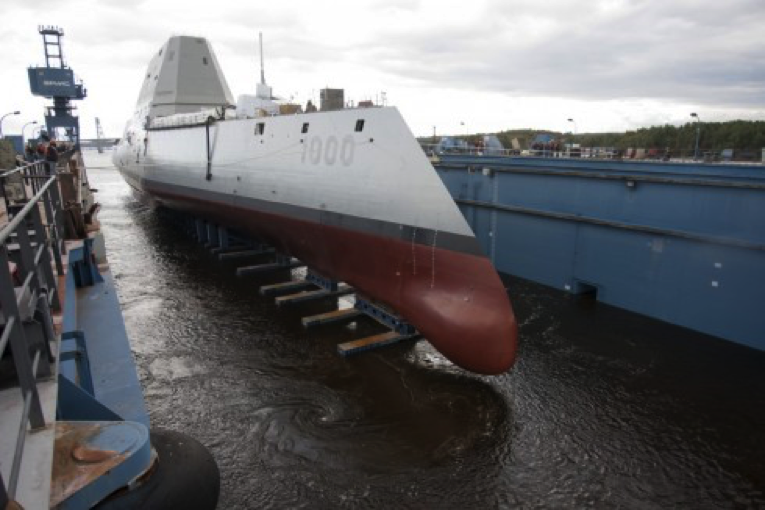
Fig 3: Zumwald Destroyer launched from floating dock (photo courtesy US Navy/General Dynamics Bath Iron Works)
MODULAR FLOATING STRUCTURES
While a plate-like floating structure may be of any size or shape, for ease of launching and towing they are formed with smaller modules. Modules are connected afloat at their destination.
While steel is commonly used for barges and modular pontoons, reinforced concrete lend itself better to production processes which are repetitive. In most cases, it is a more cost effective solution. The materials involved are cheaper and casting concrete is a lot less skill intensive than welding steel. Both steel and concrete are suitable for structures with service life of 50 or more years. State-of-art concrete floating structure design makes use of post-tensioning techniques that minimise risks of cracking and associated ingress of salts. With newly developed technologies maintenance free high strength concrete without rebars may be designed for 100-year life.
Methods of connecting modules depend on the wave environment and payloads. Connections are generally rather uncomplicated such as that used in the floating stage in Singapore. When very huge loads are moved across the deck, the platform may rotate noticeably. To counter this ballast water in the tanks may be shifted progressively to keep the platform level. The sidewalls outer peripheral modules are designed to receive fenders. The decks are screed with a fall so that precipitation is directed to tanks below deck for hull cleaning and other uses.
For application as a dockyard facility, the floats mostly behave as a rigid buoyant body. However, for light loads the floats are “thin”. Such mat-like floats need to be analysed for their hydro-elastic response. Kirchoff plate theory is used to model the entire structure as a single plate (see examples in works quoted in the reference in the appendix) while the water wave is modelled using linear wave theory. Usually the frequency domain approach is used, but more sophisticated hydro-elastic analyses are possible to determine deflections and stresses of secondary structural components of the complete 3D floating structure.
Khabakhpasheva and Korobkin (2002) propounded an auxiliary floating structure that is connected to the main floating structure by a hinge joint or rigid mechanical joint in order to reduce the deflection of the main floating structure. Wang et al. (2009) then proposed a novel way in reducing the hydro-elastic response of VLFS through the design of semi-rigid mechanical joints that connect the auxiliary structure to the main floating structure. The design involves suitable rotational stiffness and location of such mechanical joints with the view to a significant reduction in hydro-elastic response of the interconnected floating modules.
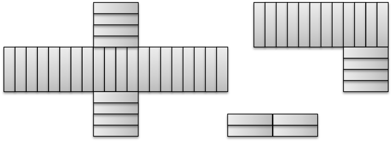
Fig 4: Modular floating bases in various stages of development: 100 x 400, L shape 600 x 200 plus 200 x 200, Cross shape 1000 x 200 plus 200 x 200 pieces
The modules may be joined form assemblies of any rectilinear shape. Crucifix- or H- shapes usually provides a high berth length to footprint area ratio. Fig. 4 shows 4,000 metres of berth space is possible with a 35-ha footprint and 1,200 metres with a 5-ha footprint. Such high berths to land ratios are hardly possible onshore.
It is not a problem to erect heavy plate, pipe or machine shops on a floating platform. One need not be concern about rolling or pitching when large heavy overhead cranes traverse the workshops. During the design stage all possible movements of heavy load will be considered to ensure that any rotation or oscillation of the platform will be kept to an imperceptible level.
Roads may be designed to carry wheeled loaders of a hundred tons if necessary. Drains will be incorporated on the deck to channel precipitation to tanks beneath the floats for industrial application, ship hull washing or firefighting.
ILLUSTRATIVE EXAMPLE OF A FLOATING NAVAL BASE
Based on data gleaned from the Internet and from Google Earth, we have created a 3-D visual to show how a comprehensive floating naval base could fit into the area within the breakwater already constructed at Karwar, by the Indian Navy. We believe such a concept would meet the requirements for berths, docks, workshops and accommodation spaces for current and future requirements. Please refer to Fig. 5.
Any subsequent expansion modules is fabricated, and completely outfitted at some location away from the base. Such new fully outfitted addition is towed to the base, moored and ready for service in a matter of days. In the conventional base, any additional facility would have to be built on site with construction crew and equipment requiring access to the base, which compromises security and interferes with naval operations.
In addition to Karwar, India is considering an eastern seaboard base at Visakhapatnam to counter the naval posturing of China. Using the VLFS technology parts of the Karwar dockyard may be shifted to the eastern seaboard to meet threats on the east coast, reasonably assuming that threats from east and west are unlikely to be equally serious at any given time.
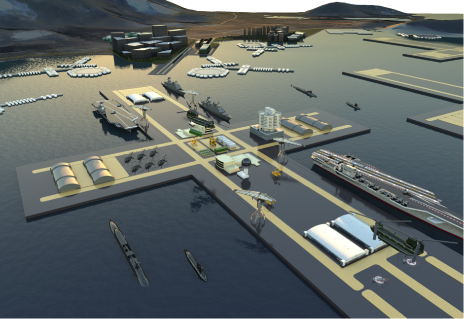
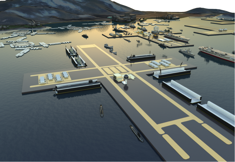
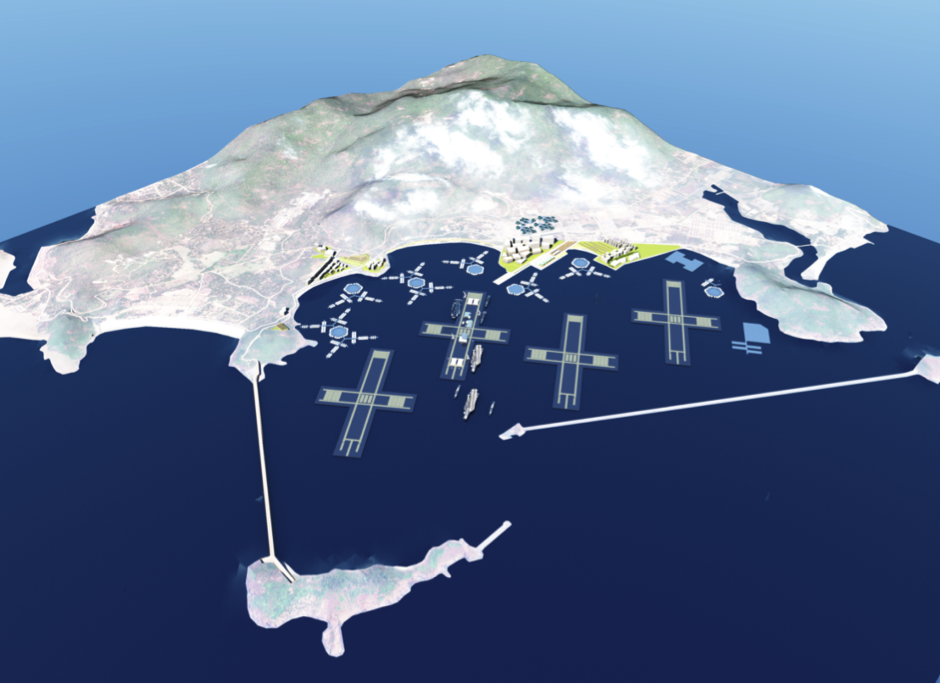
Fig 5: Visuals of Karwar alternative floating naval base
CONVENTIONAL DOCKS, WHARVES AND JETTIES
Conventional maritime structures, founded on the ground or supported by piles, such as wharves, piers or jetties and, above all, dry docks can present technical challenges. Reasonably firm ground conditions at not too great a depth are required to support piled structures. Quays and wharves likewise require firm ground conditions for stability and for the fill behind them not to be subject to settlement. Most suitable sites with the necessary sheltered water in the developed world have long since been built on.
Dry docks present a further problem in that it is necessary to dig a large excavation and dewater it in order to build the dry dock. As they are located close to open water a relatively impermeable soil is required and even rock can be problematical if heavily fissured or has cavities as in karstic limestone. Traditionally a suitable site for a dry dock would be found and a shipyard would be built around it. Nowadays such enviable sites have largely been taken and dry docks are built on increasingly technically challenging sites. There have been disasters along the way as the ground, despite extensive prior investigation, can throw up nasty surprises.
Many docks and quays in London, Tokyo, New York and Singapore had to be demolished. Demolishment adds cost to their life cycle cost. Floating structures have many advantages and have residual values.
We need to recycle more if we are to save Planet Earth. All old floating structures can always find a new purpose. A naval base float need not be demolished after it has served its time. They may be repurposed as platforms on which schools, hospitals, houses, power plants, farms or drinking water reservoirs may be erected for use in areas where people badly need them.
CONCLUSIONS
VLFS (very large floating structures) have opened up a new range of possibilities to construct traditional facilities in the sea using the principle of buoyancy. These facilities include bridges, ports, offshore rigs on the one hand and stadiums and theatres on the other. They are found in seas, lakes and fjords in the north and south hemispheres. We believe navies of the world have much to gain to embrace this solution.
FOOTNOTE
[1] It was reported in Malaysia (The Sun, December 12, 2015), that China will build a floating mega port in the Strait of Mallacca, overtly as a commercial undertaking. One has to ask why it want to build a port so far away.
REFERENCES
- ABAM Engineers, Valdez, Concrete Floating Container Terminal at Valdez, Alaska Publication #C830131, 1983
- Hermans, A.J. (2000). A boundary element method for the interaction of free-surface waves with a very large floating flexible platform. J. Fluids Struct., 14;943-956.
- Inoue, K., Nagata, S. and Niizato, H. (2003). Stress analysis of detailed structures of Mega-Float in irregular waves using entire and local structural models. Proc. 4th Int. Wksp Very Large Floating Struct., Tokyo, Japan, 219-228.
- Inoue, K. (2001). Stress analysis of Mega-Float in waves by two-step method. Proc. of 20 th Int. Conf. on Offshore Mech. and Arctic Engrg., Rio de Janeiro, Brazil, June 3-8, 2001, OMAE2001/OSU-5209.
- Khabakhpasheva, T.I. and Korobkin, A.A. (2002). Hydroelastic behavior of compound floating plate in waves. J. Engrg Maths., 44;21-24.
- Kada, K., Fujita, T. and Kitabayashi, K. (2002). Stress analysis for structurally discontinuous parts in a Mega-Float structure. The Int. Soc. Offshore and Polar Engrg., 12;48-55.
- Kashiwagi, M. (1998). A b-spline Galerkin scheme for calculating the hydroelastic response of a very large floating structure in waves. J. Mar. Sci. Technol., 3;37-49.
- Kashiwagi, M. (2000). A time-domain mode-expansion method for calculating transient elastic responses of a pontoon-type VLFS. J. Mar. Sci. Technol., 5;89-100.
- Kashiwagi, M. (2004). Transient responses of a VLFS during landing and take-off of an airplane. J. Mar. Sci. Tech., 9(1);14-23.
- Kim, J.W. and Webster, W.C. (1998). The drag on an airplane taking off from a floating runway. J. Mar. Sci. Tech., 3(2);76-81.
- Koh Hock Seng and Lim Yoke Beng, Shaping the Integrated Floating Stage at Marina Bay.
- Paul Palo, “Mobile Offshore Base” with extracts from works of C M Wang and B T Wang’s “Very Large Floating Structures”
- Ohta, H., Torii, T., Hayashi, N., Watanabe, E., Utsunomiya, T. Sekita, K. and Sunahara, S. (1999). Effect of attachment of a horizontal/vertical plate on the wave response of a VLFS. In: Ertekin, R.C., Kim, J.W., editor. Proc. 3rd Int. Wksp. Very Large Floating Struct., University of Hawaii at Manao, Honolulu, Hawaii, USA, September 22-24, 1999; 265-274.
- Sasajima, H. (1999). Local structural analysis of large floating structures. In: Ertekin, R.C., Kim, J.W., editor. Proc. 3rd Int. Wksp. Very Large Floating Struct., University of Hawaii at Manao, Honolulu, Hawaii, USA, September 22-24, 1999, 2;602-606.
- Sci Tech Daily 25 June 2015 “Floating Power Plant that is safer and cheaper”
- Seto, H., Ochi, M., Ohta, M. and Kawakado, M. (2003). Hydrodynamic response analysis of real very large floating structures in regular waves in open/sheltered sea. Proc. of Int. Symp. on Ocean Space Utilization Tech., Tokyo, 85-93.
- Seto, H., Ohta, M., Ochi, M. and Kawakado, M. (2005). Integrated hydrodynamic-structural analysis of very large floating structures VLFS. Mar. Struct., 18(2);181-200.
- Takagi, K., Shimada, K. and Ikebuchi, T. (2000). An anti-motion device for a very large floating structure. Mar. Struct., 13;421-436.
- Tori, T., Okubo, H., et al, Development of a Very Large Floating Structure, Nippon Steel Technical Report 82, July 2000.
- General Dynamics US Navy videos published 17 Jan 2014 in Youtube, “Zumwalt DDG1000 Launch”
- Utsunomiya, T., Watanabe, E. and Eatock Taylor, R. (1998). Wave response analysis of a box-like VLFS close to a breakwater. Proc. of 17th Int. Conf. on Offshore Mech. and Arctic Engrg., Lisbon, Portugal, July 5-9, 1998, OMAE98-4331.
- VSL, Floating concrete structures, examples from practice. Second printing July 1992.
- Wang, C.M., Muhammad, R. and Choo, Y.S. (2009). Reducing hydroelastic response of interconnected floating beams using semi-rigid connections. Proc. of 28th Int. Conf. on Offshore Mech. and Arctic Engrg., Honolulu, Hawaii, May 31-June 5, 2009, OMAE2009-79692.
- Watanabe, E., Utsunomiya, T., Kuramoto, M., Ohta, H., Torii, T. and Hayashi, N. (2002). Wave response analysis of VLFS with an attached submerged plate. Proc. 12th Int. Offshore Polar Engrg., Kitakyushu, Japan, May 26-31, 2002; 319-326.
- Watanabe, E., Utsunomiya, T., Ohta, H. and Hayashi, N. (2003). Wave response analysis of VLFS with an attached submerged plate: verification with 2-D model and some 3-D numerical examples. Proc. Int. Symp. Ocean Space Utilisation Technol., National Maritime Research Institute, Tokyo, Japan, January, 147-154, 2003.
- Watanabe, E., Utsunomiya, T. and Tanigaki, S. (1998) A transient response analysis of a very large floating structure by finite element method. Structural Engrg./Earthquake Engrg., JSCE ;15(2):155–163.
- Washington Department of Transport, “Virtual Tour of the new SR520 floating bridge” published Nov 5, 2015 on Youtube.